What is State Diagram?
What is Activity Diagram?
- To model a human task (a business process, for instance).
- To describe a system function that is represented by a use case.
- In operation specifications, to describe the logic of an operation.
Activity Diagram vs State Machine Diagram
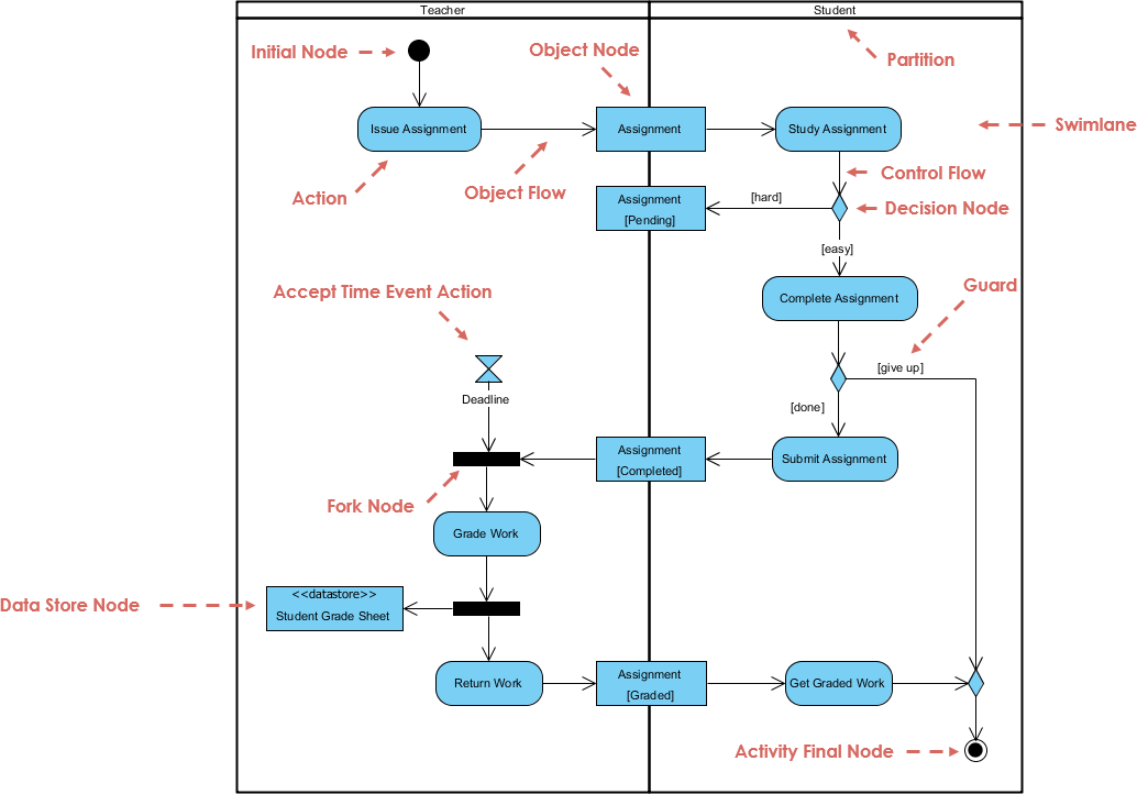
Activity Diagram
In UML semantics, Activity Diagrams are reducible to State Machines with some additional notations that the vertices represent the carrying out of an activity and the edges represent the transition on the completion of one collection of activities to the commencement of a new collection of activities. Activity Diagrams capture high level activities aspects. In particular, it is possible to represent concurrency and coordination in Activity Diagrams.Take a look at the Activity Diagram which models the flow of actions for an incident. Such an Activity Diagram focuses on the flow of data within a system.
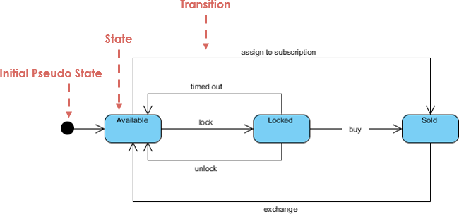
State Machine Diagram
In State Machines the vertices represent states of an object in a class and edges represent occurrences of events. The additional notations capture how activities are coordinated. Objects have behaviors and states. The state of an object depends on its current activity or condition. A State Machine Diagrams shows the possible states of the object and the transitions that cause a change in state.Take a look at the State Machine Diagram below. It models the transitioning of states for an incident. Such a state diagram focuses on a set of attributes of a single abstraction (object, system).
By using a powerful UML modeling tool you can create both types of diagrams easily.
No comments:
Post a Comment